 |
 |
 |
 |
 |
 |
در ادامه دو مقاله آنلاین درباره چگونه کارکرد ترانزیستور مشاهده خواهید کرد. این مقالات به زودی ترجمه خواهند شد.
موفق باشید
1. What is the difference between a transistor and a resistor?
Source: quora.com
Here is an explanation about the Resistor to Transistor Transition.
Let us start from a simple circuit.
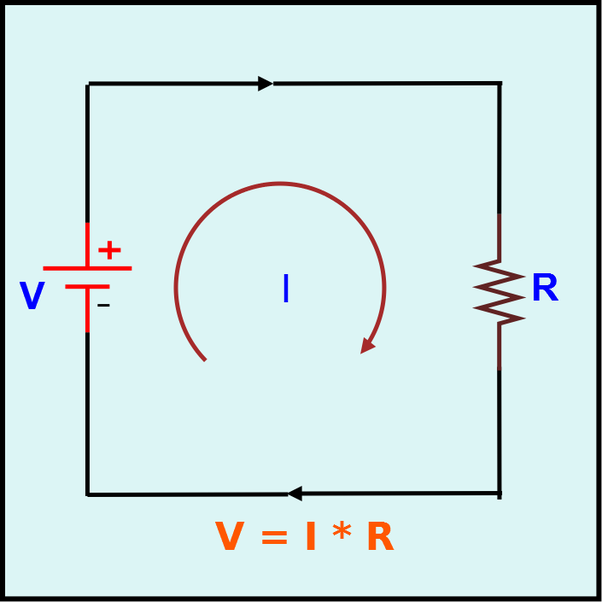
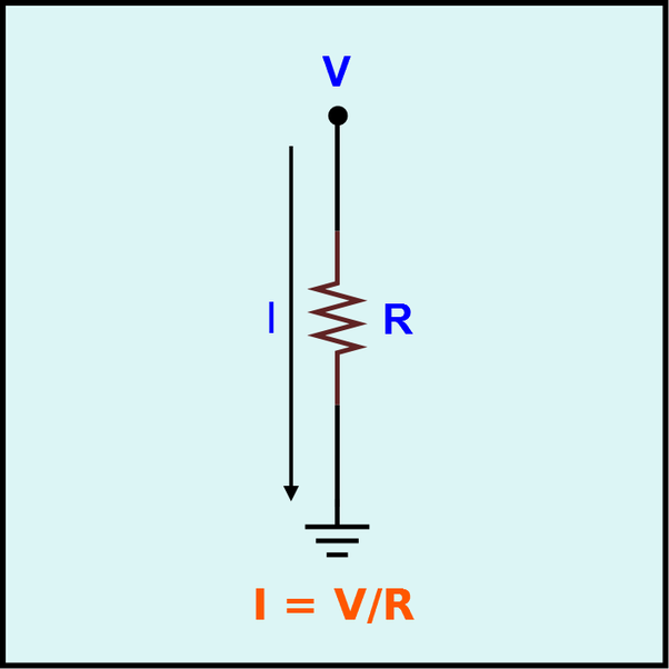
In General, Voltage source is not shown in Circuit diagrams. So let us remove the Voltage source from the circuit diagram. Also Voltage and Resistance are given, we need to calculate Current.
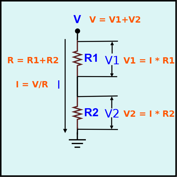
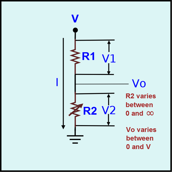
Now let us split the single Resistor in to two Resistors and connect the Resistors(R1 & R2) in Series.
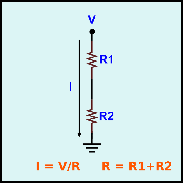
Since two resistors are connected across a single voltage source, the voltage is divided across the resistors. These voltages are V1 and V2.
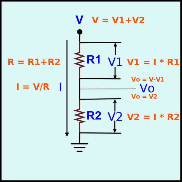
Now let us find the output voltage Vo.
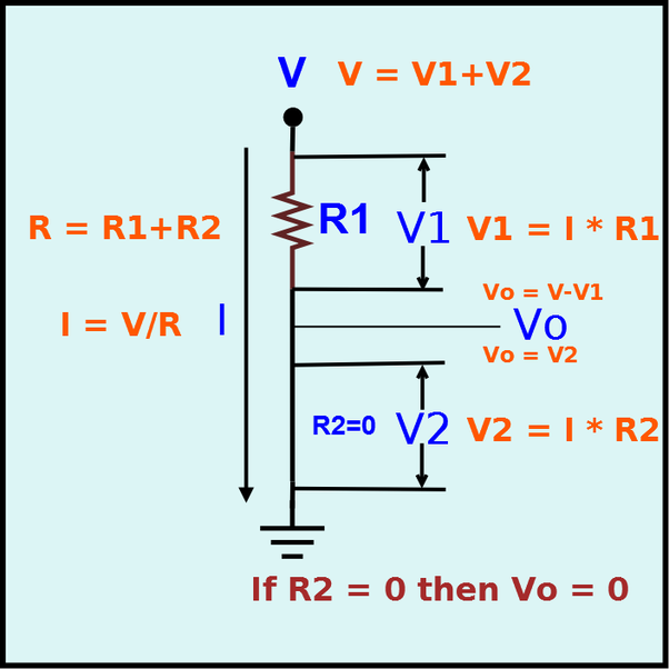
Now let us make R2 as Zero ohm. i.e. No resistance, we are going to short circuit the R2. Now the output Vo is 0V, because the output is shorted with Ground. There is no Potential Difference.
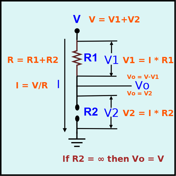
Now let us make R2 as Infinity Ohm. i.e. Remove R2 and make Open circuit. Since circuit is open no current flow. Hence I = 0A. So V2 = I * R2.
V2 = 0 * ∞ = Indeterminate. That means anything. So you can not predict. Then how will you calculate Vo? We may not able to find out V2 but we can find out V1. So Vo = V - V1. V1 = I * R1 = 0V. So, V0 = V
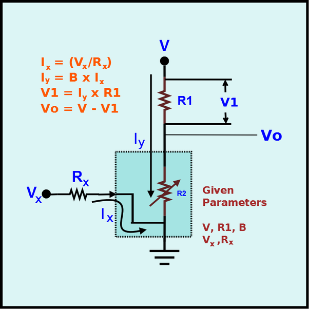
Now let us replace R2 with a variable resistor. If the R2 varies between 0 ohm to ∞ Ohm, then V0 will vary between 0 to V. So V0 can never be less than 0 and More than V.
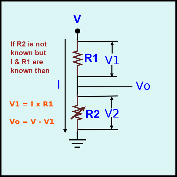
When we vary the resistance R2, the current I also varies. Let us assume we can not measure R2 but we can measure I then Vo = V - I * R1. R2 is not used in the calculation.
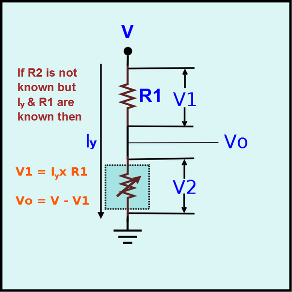
Now let us rename the Current I as Iy.
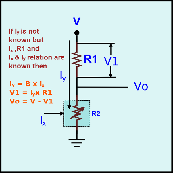
Now let us control the variable resistor using Ix. The relation between Ix and Iy is
Iy = B * Ix
Now we generate Ix using Vx and Rx.
Ix = Vx/Rx
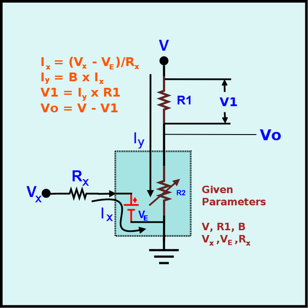
Now let us introduce a battery in between Rx and Ground. So the voltage across resistor Rx is Vx -Ve. So, Ix = (Vx - Ve)/Rx.
Now let us rename the parts.
Vx ⇒ Vb
Rx ⇒ Rb
Ix ⇒ Ib
Ve ⇒ Vbe
Iy ⇒ Ic
R1 ⇒ Rc
V1 ⇒ Vc
V ⇒ Vcc
B ⇒ β
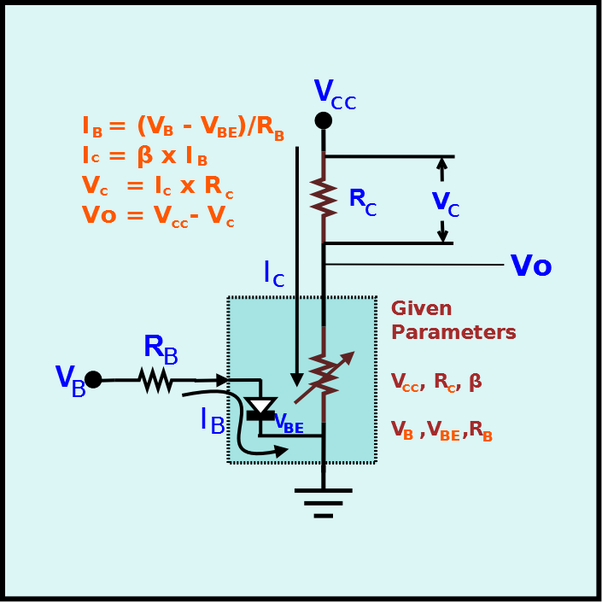
Now we change the variable resistor block as Transistor.
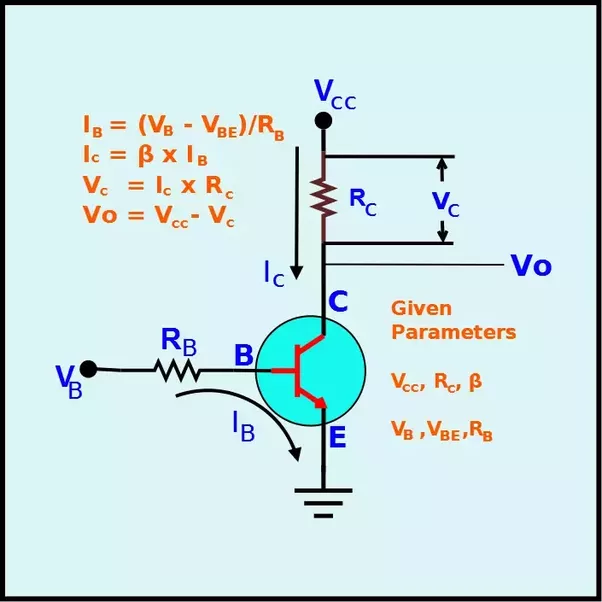
This Transistor acts as a Regulator (Variable Resistor) or a switch (ON/OFF):
The Transistor has 3 operating modes.
- Cut-off (Switch - OFF)
- Saturation (Switch - ON)
- Active (Regulator)
1. Cut-off Mode
Vb < Vbe (Generally 0.7V)So Ib = 0A
Ic = 0A
Vc = Ic x Rc = 0V
Vo = Vcc - Vc = Vcc
2. Saturation Mode
Ic > Ic.maxIc.max = Vcc/Rc
Ic = β Ib
Ic = Ic.max
Vc = Ic x Rc = Vcc
Vo = Vcc - Vc = 0V
3. Active Mode
0 < Ic < Ic.maxIb = (Vb - Vbe)/Rb
Ic = β x Ib
Vc = Ic x Rc
Vo = Vcc - Vc
0V < Vo < Vcc
When a Transistor acts as a Regulator, it is called an Amplifier.
When a Transistor acts as a Switch, it is called a Gate.
Transistor in Active Mode - Analog Electronics
Transistor in Cutoff/Saturation Mode - Digital Electronics
2. Transistors, Extending the Water Analogy.
Source: Learn [at] SparkFun
If you’ve been reading a lot of electricity concept tutorials lately, you’re probably used to water analogies. We say that current is analogous to the flow rate of water, voltage is the pressure pushing that water through a pipe, and resistance is the width of the pipe.
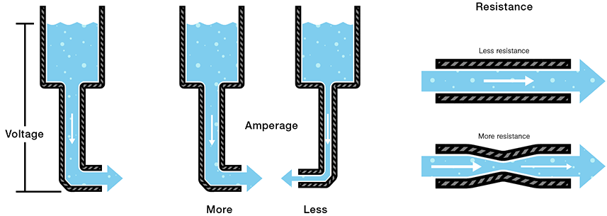
Unsurprisingly, the water analogy can be extended to transistors as well: a transistor is like a water valve – a mechanism we can use to control the flow rate.
There are three states we can use a valve in, each of which has a different effect on the flow rate in a system.
1) On – Short Circuit
A valve can be completely opened, allowing water to flow freely – passing through as if the valve wasn’t even present.

Likewise, under the right circumstances, a transistor can look like a short circuit between the collector and emitter pins. Current is free to flow through the collector, and out the emitter.
2) Off – Open Circuit
When it’s closed, a valve can completely stop the flow of water.

In the same way, a transistor can be used to create an open circuit between the collector and emitter pins.
3) Linear Flow Control
With some precise tuning, a valve can be adjusted to finely control the flow rate to some point between fully open and closed.

A transistor can do the same thing – linearly controlling the current through a circuit at some point between fully off (an open circuit) and fully on (a short circuit).
From our water analogy, the width of a pipe is similar to the resistance in a circuit. If a valve can finely adjust the width of a pipe, then a transistor can finely adjust the resistance between collector and emitter. So, in a way, a transistor is like a variable, adjustable resistor.
Amplifying Power:
There’s another analogy we can wrench into this. Imagine if, with the slight turn of a valve, you could control the flow rate of the Hoover Dam’s flow gates. The measly amount of force you might put into twisting that knob has the potential to create a force thousands of times stronger. We’re stretching the analogy to its limits, but this idea carries over to transistors too. Transistors are special because they can amplify electrical signals, turning a low-power signal into a similar signal of much higher power.
